
Coil Design/Fabrication
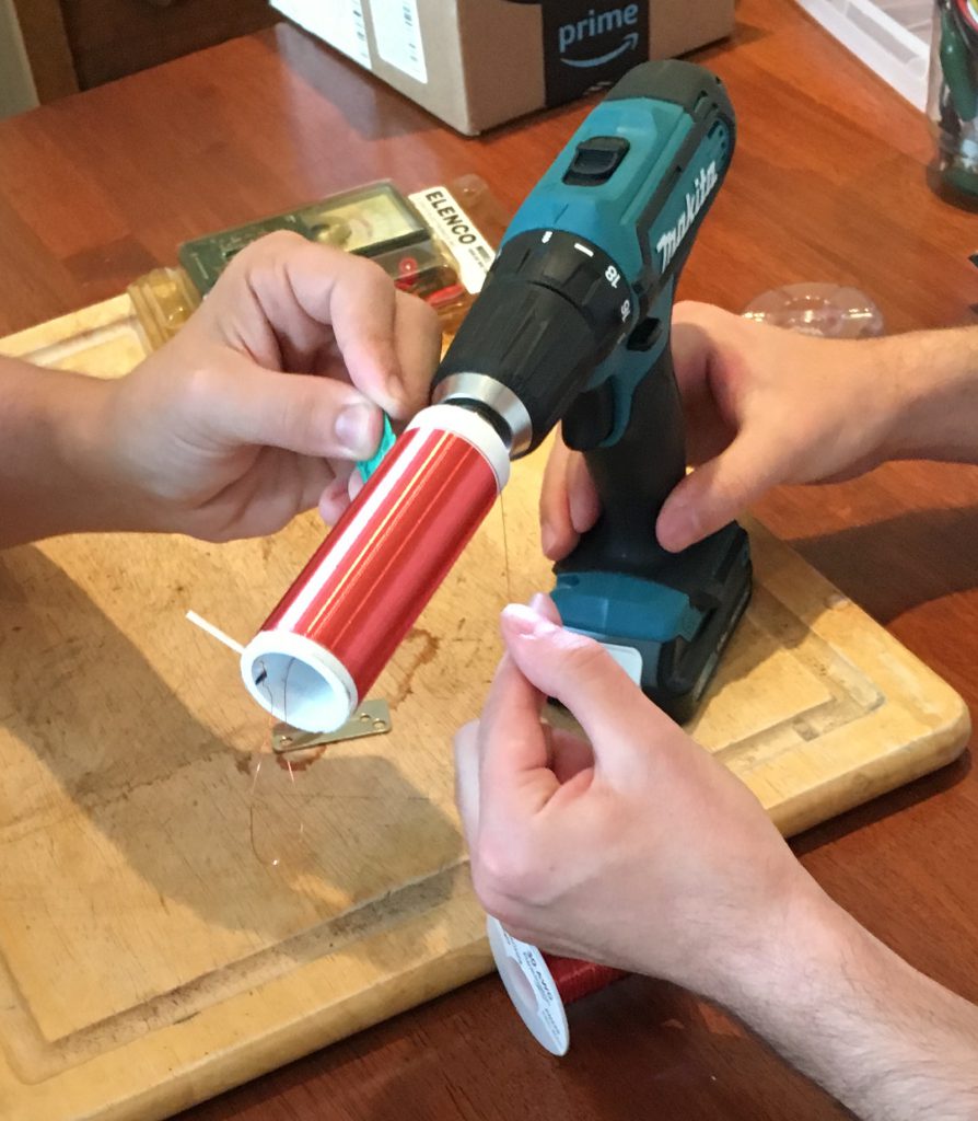
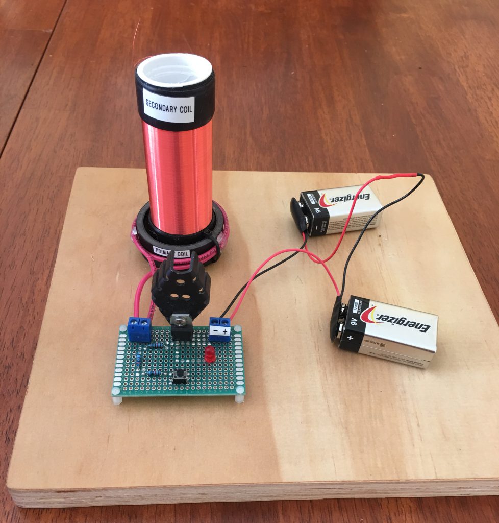
I used 30 AWG magnet wire for the secondary coil which has thin enamel coating. This is the same wire used in motor stators. I used a cordless drill to wind the wire around a PVC pipe. I estimate that there are over 200 turns in this coil. In the primary coil I went with 2 turns of thicker 14 AWG wire. This gave me a ratio of 1:100 for the primary and secondary coils. I created a modular design that allowed me to switch out the primary coil for experimentation purposes. I tested the system with 4 and 6 turns on the primary coil but found that the 2 turn primary coil worked the best (1:100 ratio).
Circuit Design
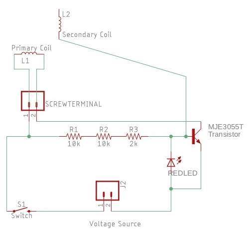
I used the “Slayer Exciter Circuit” to drive our coil because of its portability and low voltage. This circuit utilized a compact transistor instead of a spark gap to oscillate the current on the primary coil, which would induce a current on the taller secondary coil. After overheating many smaller transistors, I opted for a larger MJE3055T transistor that we could attach a heat sync to for better heat dissipation.
Circuit Prototyping
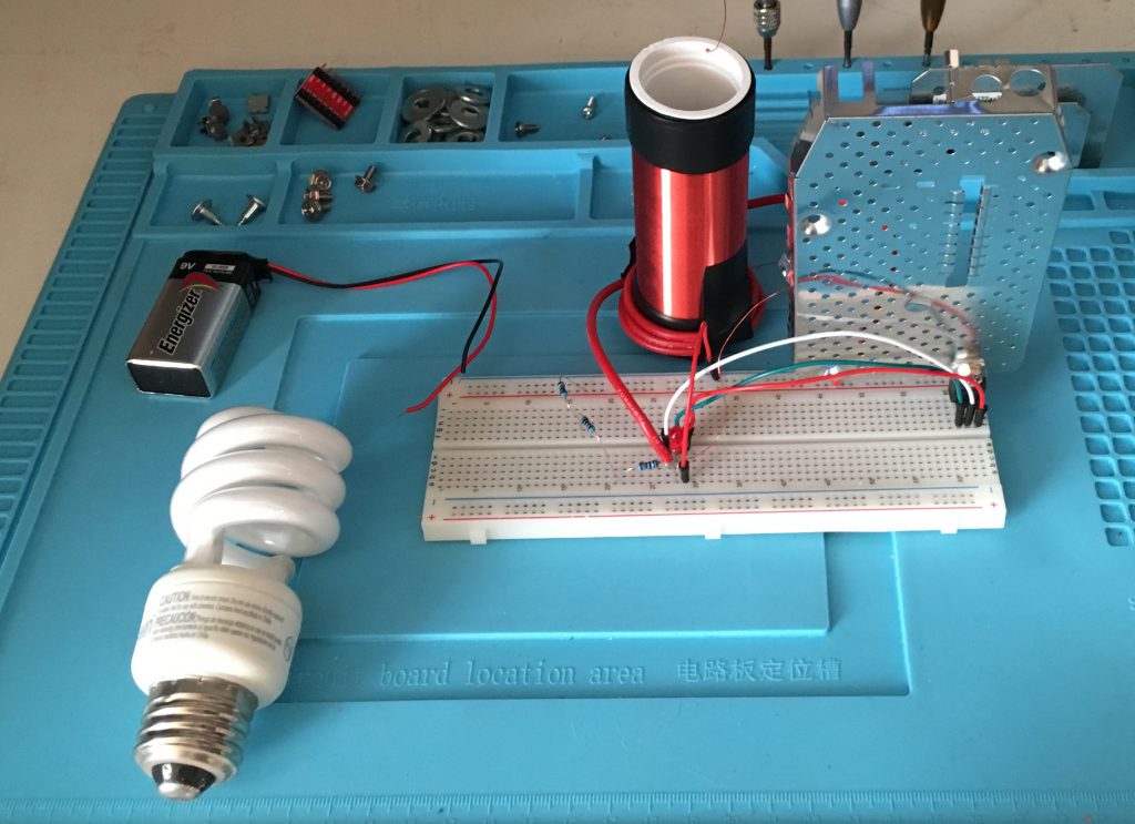
I used a breadboard which allowed me to troubleshoot circuit problems and quickly change components and connections without solder. I solved many problems such as using the wrong transistor and using too low of an input voltage. I constantly measured voltage and continuity with a multimeter across different points on the breadboard to locate points of failure.
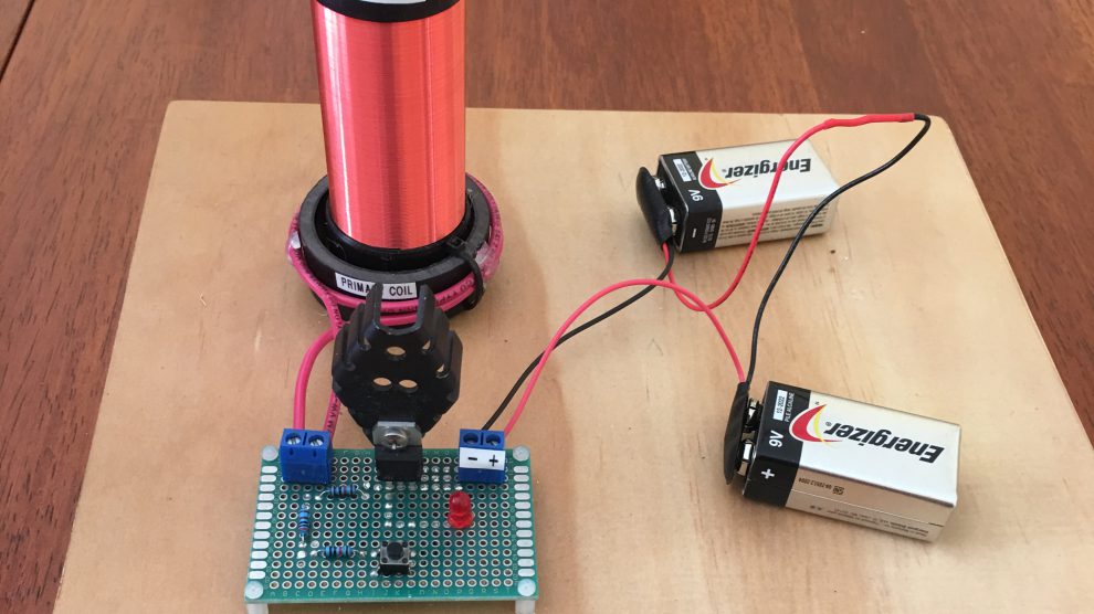
Circuit Fabrication

Putting the circuit onto through-hole circuit board allowed for more reliable solder connections vs the breadboard which was “solder-less”. I made a CAD board view where I could move components around to plan out optimal connections. Once it was planned out, I soldered it all together. I tested the coil using the new soldered circuit and it was way more reliable. We even saw the flame arc that we could not see using the breadboard circuit.
Lessons Learned/Improvements
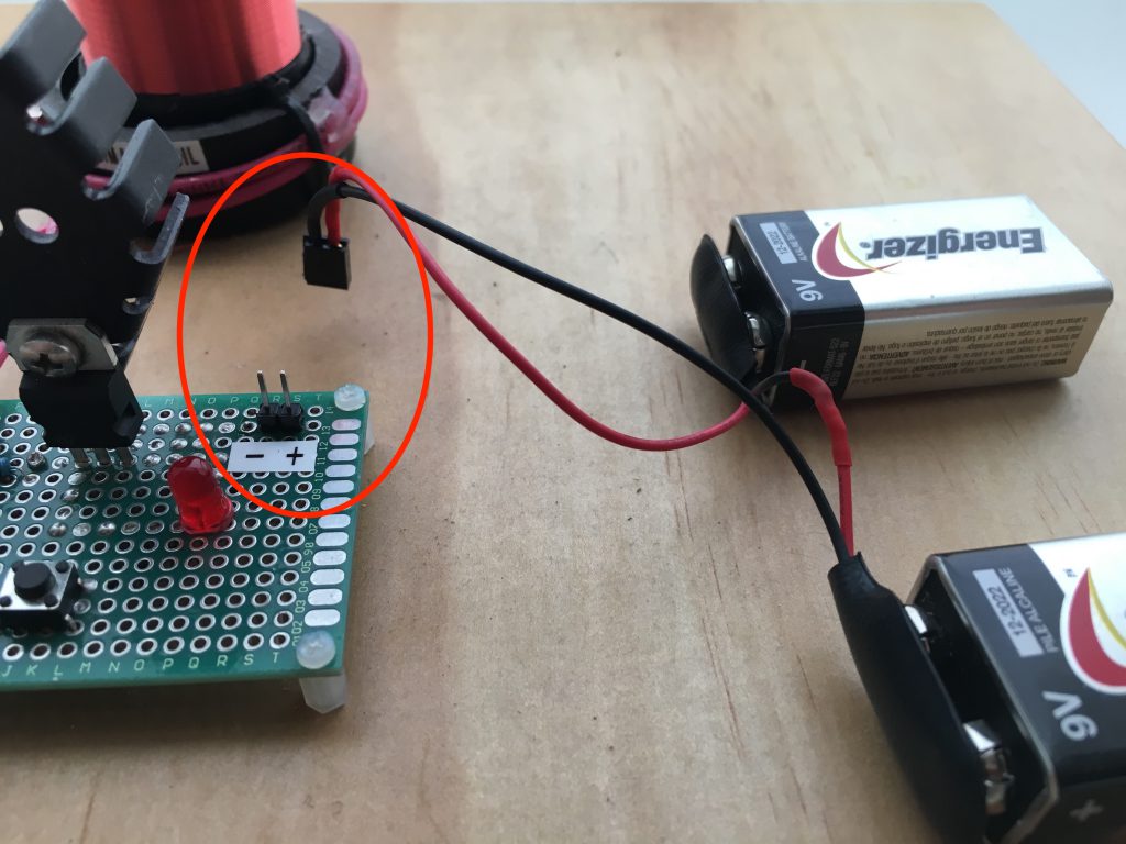
I upgraded the power connector to an easier, more reliable pin connection. In the future I would find a way to automate the drill as holding down the trigger for an hour was fatiguing. I would also 3D print a better device for attaching the drill to the pipe as the stepper bit was not completely secure. When fabricating the circuit, I would use solid core wire for making jumper connections on the final circuit board as it is easier to hold in place when soldering it on the board. I also learned the hard way that it is important not to cut off component leads as they are the easiest way to bridge solder connections across holes as solder doesn’t not stick in between the holes on the board without a conductor bridging the gap.